Pick and place machine
The main objective of the project was to create a solid model assembly for a Pick and Place (PNP) machine using Solidworks. We started by first creating a list of basic engineering specifications. Then, each team member was tasked with conducting research on different parts of a milling machine, as well as different designs of PNP machines. Once the research was collected, the engineering specification were refined. The team then brainstormed to generate four candidate designs. Based on the engineering specifications, the benefits and drawbacks of different designs were identified, and accordingly, a 3-axis PNP Machine box design with slider rail movements in X and Y direction was chosen as the final design solution. Based on the research conducted, material, component and cost analysis of the final design was conducted to create the 3D model.
First sketches


Main Candidate and components
We selected the Box Design as the main candidate after using ranking chart system. Each design was assessed based on the criteria of durability, cost, feasibility, efficiency.
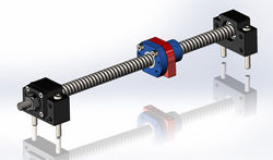
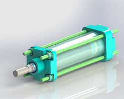
Each of the components - from the placing mechanisms to the reel feeders - of the PNP were detailed in their uses, choice of specific types and materials, as well as cost considerations, accompanied by an in-depth explanation of the safety factors that were considered to ensure that our design abides by engineering standards, codes, and regulations required.
 |  |
|---|---|
 |  |
FINAL SOLIDWORKS MODEL
